
I was inspired to do this project after going to Bonnaroo for the first time last year. The idea I had was to take a programmable belt kit, hook it up to an Arduino microcontroller and microphone and make a wearable VU meter.
Parts used for this project:
1 x digital programmable LED belt kit: http://www.adafruit.com/products/332 ($60)
1 x Arduino Duemilanove (no longer sold by Adafruit, new model is Arduino Uno R3): http://www.adafruit.com/products/50 ($30)
1 x Inex Robotics ZX-Sound detector board: http://www.robotshop.com/inex-sound-detector.html ($8)
The first step is to assemble the LED belt kit which means soldering the connector leads onto the end of the belt, programming the belt with the demo code from Adafruit and verifying the function of the belt. Instructions for this can be found here: http://www.ladyada.net/make/ledbelt/
When you’re done putting the belt together and running the demo code, you’ll have something that looks like this:
Note: the kit comes with an ATMega32u4 microcontroller, but I switched everything over to the Duemilanove after verifying the functionality of the belt. I did this for a few reasons, but the primary one was that the ATMega32u4 is annoying to program. Every time you want to update the code, you have to press the reset button shortly after hitting the compile button in the IDE. If you don’t do this correctly or your computer is slow, you can’t program the device. I was able to get this to work on a Macbook Pro, but my Windows XP machine did not play nice.
Once that is done, you will want to hook up the sound detector board to the Arduino. I connected the sound board to the Arduino (+5V, GND, analog input pin 0) with jumper cables, modified a simple analog input program that ships with the Arduino IDE to read the input from an analog pin and then display it out on the serial port. Once that function was verified I wrote a bit of code to do something useful with the readings coming from the sound detector board.
The first iteration of code just had the LEDs light up red and go from one end of the belt to the other with the volume detected by the microphone:
That worked, but why limit the belt to just red LEDs when it can do so many other colors? There was a bit of code in the Adafruit examples that demonstrated how to cycle the colors of the LEDs through as if going through a colorwheel. I modified that to cycle all the LEDs in a colorwheel instead of having the rainbow effect chase horizontally on the belt. This revision also included updating the VU meter code to start the VU meter in the center of the belt and go out towards the sides instead of going from one side to the other. That way, when the belt is worn it looks a bit better. With that code working, the belt was ready:
The finished Arduino code for this project can be found on Github here: http://github.com/Kabong/VUMeterBelt/blob/master/VUMeterBelt.pde
If you have any questions, comments or do something similar using this information please let me know, I’d love to see what you come up with!
November 3, 2013 update: Mark Warbington emailed me this video of his Halloween costume with a LED chainsaw that used some code from the Bonnaroo belt. Very cool! Thanks for sharing the video Mark!

Pingback: Bonnaroo Belt, A Wearable VU Meter « adafruit industries blog
Hello Pierre. Your belt modification project has me stoked! I’m about to order all the needed components to do something similar for my first Burning Man. I have question that about the wiring of the power that has me very puzzled. By watching the video, am I wrong in thinking that you have a red wire going into the VIN pin? Do you use the 4XAA pack from the Adafruit Belt kit? If so, how do you power the Arduino? I thought the VIN needed an higher voltage and that the LEDs cant take more than 5v. In any case you can see I’m very confused about the”powering it up notion”. If you could give me some pointers (or a rough wiring schematics) I’d be extremely grateful!
Thanks a lot.
Hello Philippe!
I am indeed using the 4xAA pack that came with the belt kit from Adafruit. The LED belt, Arduino and ZX-Sound module are all powered from that one source. The way I currently have it wired is as follows:
+5V from 4xAA battery source goes to VIN of Arduino
GND from 4xAA battery source goes to GND of Adruino
LED belt is attached to the 6-pin ICSP header using the cable provided by Adafruit in the kit as per the Adafruit LED belt assembly/walkthrough guide.
+5V of ZX-Sound module is attached to +5V of Arduino
GND from ZX-Sound module is attached to GND of Arduino
Signal from ZX-Sound module is attached to Analog In 0 of Arduino.
Note that I think I switched two of the lines of the ICSP header when I was soldering the connector to the belt, so if you use the code I uploaded to GitHub, you may need to update the I/O line definitions.
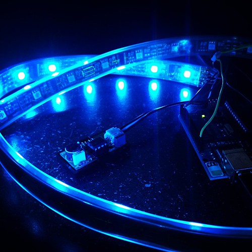
I’ve uploaded a picture of the how I have it setup to hopefully clarify a bit as well (click for fullsize):

Let me know how your project turns out or if you have any other questions!